Tools suggested are a DVOM, a couple of paper clips or suitable jumper leads and a floor jack or a partner to read the meter while speed sensor testing. Never mind a test light as Bentley suggests, it just cannot give you accurate enough answers.
Most all testing will be done at the plug for the cruise control unit.
There are eight terminals in cruise control plug, we'll use the same numbers as the Bentley.
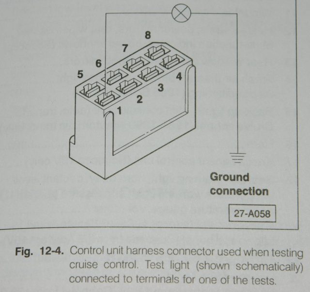
Pin 1 should have key on power from the cruise control switch, if the car has an automatic trans, the shift lever will need to be in D or 2. This same power source should also feed power to the vacuum control motor.
Pin 8 should be ground.
Pin 2 should have power when set is selected.
Pin 6 should have power when resume is selected.
Pin 3 should be grounded through the brake light bulbs. Expect resistance of very few ohms through the bulbs in parallel. If you have LED replacement lights you are on your own. When either the brake or clutch pedal vent valve switches are activated this circuit should go open. There is a safety redundancy built into this circuit should the vent valve switches fail to open, brake light power will be fed to this circuit.
Pin 4 when grounded should activate the pump motor.
Pin 7 when grounded should activate the vacuum holding valve in the pump assembly.
When pins 4 and 7 are grounded simultaneously the vacuum servo should operate and open the throttle. If the brake and/or clutch pedals are operated during this test the vacuum servo should release. Hose leaks, leaky vacuum vent valves at the pedals and leaky servos are common reasons to fail this test.
Pin 5 is the speed sensor input. For inductive senders use a low range AC voltage scale between pin five and ground. AC voltage should increase as speed increases.
For Hall senders as used with MFA displays look for a square wave or pulsed DC voltage of either five or 10 volts.
©2006, Ron, tolusina on the 'tex.